1、 Precautions for switching on and off LED display screen:
Switch sequence:
When turning on the screen: turn on the phone first, then turn on the screen。
When turning off the screen: turn off the screen first, then turn it off。
(Turning off the computer first without turning off the display screen can cause high highlights on the screen, burn out the light tube, and have serious consequences.)
2. The time interval between opening and closing the screen should be greater than 5 minutes.
3. After entering the engineering control software, the computer can only be turned on and powered on.
4. Avoid turning on the screen in a fully white state, as the system's impulse current is at its maximum.
5. Avoid opening the screen in a state of loss of control, as the impact current of the system is at its maximum.
Computer A did not enter control software or other programs;
Computer B is not powered on;
The power supply of the C control section is not turned on.
6. When the ambient temperature is too high or the heat dissipation conditions are not good, it should be noted not to open the screen for a long time.
When a very bright line appears on a part of the electronic display screen, attention should be paid to turning off the screen in a timely manner, and it is not advisable to turn on the screen for a long time in this state.
8. If the power switch of the display screen trips frequently, the screen body should be checked or the power switch should be replaced in a timely manner.
9. Regularly check the firmness of the attachment. If there is any looseness, please adjust it in a timely manner, and reinforce or update the suspension components.
10. Based on the environmental conditions of the large screen display screen and control part, avoid insect bites, and if necessary, place rodent repellents.
2、 Precautions for changes and changes in the control section
1. The power lines of the computer and control parts should not be connected in reverse, and should be strictly inserted in the original position. If there are peripherals, the casing should be tested after connection is completed
Is it electrified.
2. When moving control equipment such as computers, the connection wires and control boards should be checked for looseness before power on.
3. The position and length of communication lines and flat connecting wires cannot be changed arbitrarily.
4. If abnormal phenomena such as short circuits, trips, burning wires, and smoke are found after movement, the power test should not be repeated, and the problem should be promptly identified.
III. Precautions for Software Operation and Use
1. Software backup: WIN2003, WINXP, applications, software installation programs, databases, etc.
It is recommended to use the "one click restore" software for easy operation.
Proficient in installation methods, original data recovery, and backup.
3. Master the setting of control parameters and the modification of basic data presets
Proficient in using programs, operations, and editing.
Regularly check for viruses and delete irrelevant data
6. Non full-time personnel are not allowed to operate the software system.
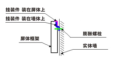
1) Wall mounted (wall mounted)
Suitable for displays below 10 square meters. The requirement for the wall is to have concrete beams at the solid wall or suspension point. Hollow bricks or simple partitions are not suitable for this installation method.
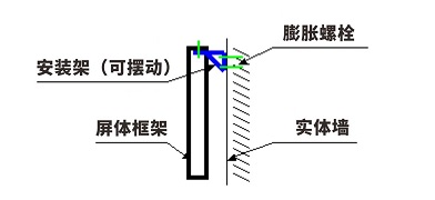
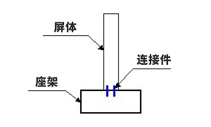
2) Rack mounting is suitable for displays over 10 square meters and is easy to maintain. Other specific requirements are the same as wall mounting.
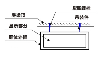
3) Hoisting is suitable for display screens below 10 square meters, and this installation method must have a suitable installation location, such as a crossbeam or lintel above. And the screen generally requires a back cover.
To ensure that our product can be used normally under reasonable conditions and receive your recognition of the product, we will briefly describe the product's usage process and precautions. Please read carefully before proceeding with the installation and debugging of the LED display screen.
1. List of hardware devices used:
LED display signal connection cable, power connection cable, system control card (loaded in the computer), system receiving card (loaded in the LED display screen), desktop computer (including DVI video output and serial port), display screen and related accessories
2 Usage process
The hardware installation steps are as follows:
1. Insert the DVI display card into the AGP slot on the motherboard and install the driver for the card;
2. Insert the data collection card into an empty PCI slot (if used);
3. Connect the data acquisition card and display card together using a DVI cable;
4. Connect the control line to the serial port (Rs232) (optional, required for the Lingxingyu system);
5. Connect the network cable to the receiving card; (Specific number of items according to engineering drawings)
6. Check the connection and proceed with setup or power on debugging.
The software installation steps are as follows:
1. Installation of graphics card driver
Insert the graphics card driver CD into the CD drive to automatically enter the installation state. Please follow the prompts to proceed. Install DirectX8.1 first; Then install the driver program; Finally, install the control panel.
2. Playing software
Install a large screen dedicated playback and setup software LED studio, or other control software. Insert the application software CD included with the screen into the CD drive, and copy or install all programs onto the computer.
3 Electronic screen operation steps (important)
1. Open screen: Please open the computer first, and then open the electronic screen. Connect power to each device (ensuring that the input voltage meets product requirements), turn on the LED screen (there will be regional flashing when the screen is powered on, indicating that the screen is powered on), turn on the computer, and make sure that the graphics card settings are correct (incorrect settings will result in no display screen, i.e. black screen), open the control software, and set the basic pixel size and display area (this setting does not affect the display of the LED display screen)
2. Turn off the screen: First, turn off the LED screen power, turn off the control software, and then turn off the computer correctly.
4. Identify issues
1. Check whether the wiring methods are correct, including the connection of the strong current part (the weak current part has been tested by the production enterprise), the signal connection, mainly for the correct input and output directions of the system receiving card, and the direction indication on the receiving card. Is the system connection correct (please refer to the system connection instructions)? Has the computer software section been installed, including the settings of the graphics card (please refer to the graphics card settings instructions) and the installation of control software.
5. Precautions
1. Follow the operating steps in the User Manual;
2. Moisture proof, humidity requirement: At the highest operating temperature, the LED display screen should be less than 92% relative humidity
3. The temperature is appropriate, and the temperature requirements are: working environment temperature -20 ° C ≤ t ≤ 80 ° C, storage environment temperature -40 ° C ≤ t ≤ 60 ° C
4. The power supply should meet the requirements: the power supply voltage of the LED display screen: 220V ± 10% Frequency: 50HZ ± 5% Safe and reliable ground contact, reliable isolation between the ground wire and the zero line, and the power supply should be connected away from high-power electrical equipment.
For other issues in the operation process, please refer to our relevant instructions. If you have any further questions, please contact us.
Outdoor LED display screen (module) daily maintenance instructions
Multiple modules that are continuously not lit or have abnormalities: Check if the wiring and power cord of the first abnormal module in the signal direction are in good contact. If the module does not have an LED on, it indicates that there is no power input. Please check the power part (which can be checked with a multimeter). If there are patterns (bright spots with mixed colors), it indicates that there is no signal input in the module. Please check if the input end of the wiring of the first abnormal module is tightly connected, It can be tested multiple times by plugging and unplugging, and if the problem persists, a new cable can be replaced.
2. Single module not lit: Check if the power supply of the module is good, mainly to check if the power socket on the module is loose. If there is color confusion or inconsistency in the entire module (but with signal input and correct image), it is due to poor contact in the signal transmission line. Reinsert or unplug the line, or replace the tested line. If there is still the same problem with the replaced cable, please check if there is a problem with the interface of the PCB board.
3. Detection method for single light failure: Use a multimeter to check if the LED is damaged. If the light is damaged, replace it according to item 5 below. Specific lamp measurement method: Set the multimeter to resistance X1, connect the black lead of the pointer type multimeter to the positive pole of the LED, and connect the red lead to the negative pole (the black lead of the digital meter is connected to the negative pole, and the red lead is connected to the positive pole). If the LED is on, the measured lamp is good; if the lamp is not on, the measured lamp is bad.
4 LED bad point maintenance (out of control point): After single lamp detection and confirmation of LED damage, the following maintenance methods can be selectively used according to actual needs.
4-1 Front maintenance: Use a screwdriver of the corresponding model to remove the screws fixing the face shield from the front (please keep the screws), remove the lower cover, and replace the light (please follow the lamp replacement method below). After replacing the light and sealing the gel, restore the original face shield, tighten the screws (please be careful not to press the light when installing the screws), and finally, if there is any residual gel on the LED surface, please carefully remove the gel.
4-2 Back maintenance: Use a screwdriver of the corresponding model to remove the screws from the back (be careful to keep the screws), unplug the signal cable, and for safety reasons, do not unplug the power connection cable to prevent accidents. Carefully remove the module from the sheet metal hole and move it to the back of the box. Then, follow the front maintenance method to maintain and replace the light for a single module (please follow the light replacement method below) or repair other issues.
5. Lamp replacement: Use sharp tools (such as tweezers) to remove the glue around the damaged LED and make the LED pins clearly visible in the line of sight. Use tweezers to clamp the LED with your right hand, and use soldering iron with your left hand (the temperature is about 40 degrees Celsius, too high a temperature will cause damage to the LED) to contact the soldering tin. Leave it for a short time (no more than 3 seconds, if it exceeds the time but does not meet the disassembly requirements, please cool it down before trying again) to melt the soldering tin, Use tweezers to remove the LED. Insert the LED light that meets the requirements into the hole of the PCB circuit board correctly (the long leg of the LED light is the positive pole, the short leg is the negative pole, the "square hole" on the PCB is the LED positive pole pin jack, and the "round hole" is the LED negative pole pin jack), melt a small amount of solder wire, stick it to the soldering iron head, adjust the LED direction with tweezers to make it stable, solder the solder to the connection between the LED and PCB, and seal the LED with the same type of gel (pH=7).
System Troubleshooting - Eight Step Troubleshooting for LED Display System Faults
Step 1: Check if the graphics card settings section is set properly. The setting method is available in the CD electronic file as needed, please refer to it.
Step 2: Check the basic connection of the system, such as whether the DVI cable and network cable socket are correct, the connection between the main control card and the computer PCI socket, and the serial cable connection. The connection method has already been illustrated, please refer to it carefully
Step 3: Check if the computer and LED power system meet the usage requirements. When the power supply of the LED screen is insufficient, it will cause the screen to flicker when the display is close to white (with high power consumption). A suitable power supply should be configured according to the power supply requirements of the box.
Step 4: Check if the green light on the sending card is flashing regularly. If it does not, restart and check if the green light is flashing regularly before entering Win98/2k/xp. If it is flashing, check if the DVI cable is connected properly. If the problem is not resolved, replace the sending card, graphics card, and DV cable I separately and repeat step 3.
Step 5: Please follow the software instructions to set up or reinstall before setting up until the sending card's green light flashes. Otherwise, repeat step 3.
Step 6: Check if the green light (data light) of the receiving card is flashing synchronously with the green light of the sending card. If it is flashing, turn to Step 8 to check if the red light (power supply) is on. If it is on, turn to Step 7 to check if the yellow light (power protection) is on. If it is not on, check if the power supply is reversed or there is no output from the power source. If it is on, check if the power supply voltage is 5V. If it is turned off, remove the adapter card and cable and try again. If the problem is not resolved, it is a receiving card fault, Replace the receiving card and repeat step 6.
Step 7: Check if the network cable is properly connected or too long (standard Category 5 network cable must be used, and the longest distance of the network cable without a repeater is less than 100 meters). Check if the network cable is made according to the standard (please refer to the system installation and settings). If the problem is not solved, replace the receiving card and repeat step 6.
Step 8: Check if the power light on the large screen is on. If it is not on, go to Step 7 and check if the adapter interface definition line matches the unit board.
Note: After most of the screens are connected, there may be a partial lack of image or blurred screen in a certain box. Due to the loose connection of the RJ45 interface of the network cable or the lack of connection to the power supply of the receiving card, the signal may not be transmitted. Therefore, please unplug or replace the network cable or plug in the power supply of the receiving card (pay attention to the direction) to solve the problem
ABOUT US
[Follow WeChat QR code]

[Follow website QR code]